AgOpenGPS How to build Section Control

del_boy

Member
Location
Herefordshire
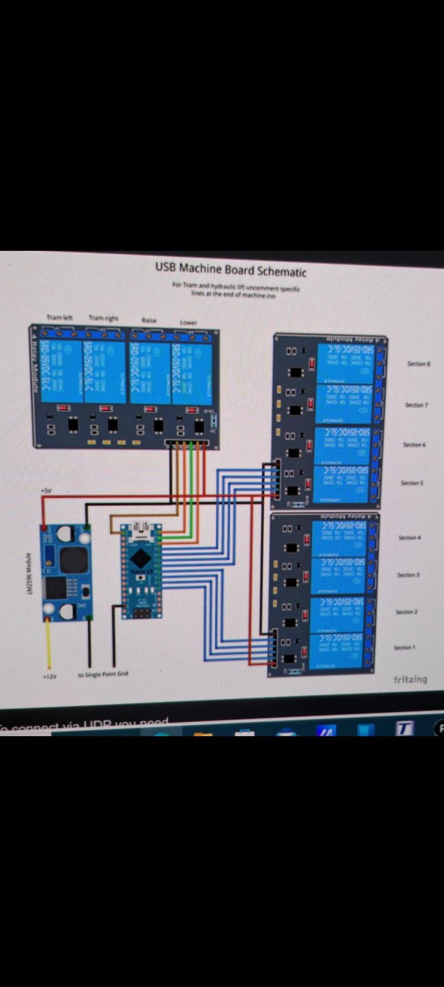
I'd getting a couple of boards in the link I posted above and swap them over. I've made a section control with 8 relays which, although I've not put on the machine yet, works fine on the bench. I think in @Andy26 original post he said you need a separate power supply for higher number of relays.
This could be why the nano has a restricted number of switchable 0v to 5v pins.as I needed 12 pins @Andy26 advised me on some code altering in the arduino nano which allowed it to add a few extra pins to switch 5v
 

del_boy

Member
Location
Herefordshire
R
I'd getting a couple of boards in the link I posted above and swap them over. I've made a section control with 8 relays which, although I've not put on the machine yet, works fine on the bench. I think in @Andy26 original post he said you need a separate power supply for higher number of relays.
Right im going to give it another stab.
Ive ordered 2 8 module relay boards 5v.
A spare nano just incase
Couple of 12v to 5v converters to power the new boards.
A 4m usb cable to go from the nano on the drill to the tablet
Watch this space 🤞
 

del_boy

Member
Location
Herefordshire
Are
I'd getting a couple of boards in the link I posted above and swap them over. I've made a section control with 8 relays which, although I've not put on the machine yet, works fine on the bench. I think in @Andy26 original post he said you need a separate power supply for higher number of relays.
Are you powering the relay board itself with a 12v to 5v converter supply?
 

clbarclay

Member
Location
Worcestershire
My section control box is connected with ethernet rather than USB, so it was an obvious choice to have buck converter powering both the nano and relays.

Doing a quick search, it appears that those relays can consume 70 mA each and a nano is only rated to supply about 200 mA. It does seem that anything over 3 relays would be testing the limits of the nano without a separate power supply for the relays.
 

Andy26

Moderator
Arable Farmer
Location
Northants
My section control box is connected with ethernet rather than USB, so it was an obvious choice to have buck converter powering both the nano and relays.

Doing a quick search, it appears that those relays can consume 70 mA each and a nano is only rated to supply about 200 mA. It does seem that anything over 3 relays would be testing the limits of the nano without a separate power supply for the relays.
I think in @del_boy case the Nano is just switching the relays, so about 5ma a section, the actual relay operation should be powered by the 12v supply to the relay board.
 

del_boy

Member
Location
Herefordshire
I think in @del_boy case the Nano is just switching the relays, so about 5ma a section, the actual relay operation should be powered by the 12v supply to the relay board.
Right update.
Swapped over the 12v relay board to a 5v relay board.
Wired up the 5v coverter to the relay board to the dc+ and dc- pins.
Board lights up green.
Connected Dupont wires to the nano
When i turn 1 section on they all try and light up (currently only have 6 Connected).
That was with a genuine nano. Tried a clone copy that i put the same software on and still the same turning 1 section on lights up 6 but they are dim
I tried swapping the com high to com low and exactly the same.
When i test each pin on the nano im getting 5v to 0v when switching on every pin. This is strange 🤔
Im powering the relay board with 5v not 12v
 

del_boy

Member
Location
Herefordshire
With section 2 on the led light on relay board is the strongest and reading 4.6v. Lights 1 3 5 and 6 are also on very very dim.
With 4.6v on pin 2 the other pins are also reading a relatively low voltage and one is actually reading 0.7v which explains the dim lights.
Even though the lights are dim they are infact triggering the relay aswell.
Ive swapped back to com low on relay board and also inverted relays but still the same
 
Last edited:

del_boy

Member
Location
Herefordshire
Small voltage is getting to relay board triggering it even when switched off. If every section is off then no power goes down. As soon as you switch 1 on the others get a small current.
Swapped usb cables but still the same. Tried inverting relays aswell
20240412_105620.jpg
20240412_105612.jpg
20240412_105601.jpg
20240412_105556.jpg
 

del_boy

Member
Location
Herefordshire
No i havnt. Ive only currently got 6 out of 12 wired up. Wanted to get these going before i swap both boards over.
Its just that small voltage coming from the nano is enough. When every section is off they all read 0v when turning any section on the other 5 start reading anything from 0.04v to 0.07v 🤔
 

S.Jamieson

Member
Mixed Farmer
Ok, so I want to add simple 4 section control to my Gem Emerald sprayer.

Joystick buttons are off/on type. Push to make, push to break. 12v down the switch when on.

I have access in the fusebox to the 12v lines coming from the joystick to the ball valves - numbered 5, 6 , 7 , 8.


What do I need to do is essentially what I'm asking.
Can I keep my current joystick buttons?
 

Attachments

  • 20240412_111922.jpg
    20240412_111922.jpg
    112.9 KB · Views: 0
  • 20240412_111712.jpg
    20240412_111712.jpg
    180.7 KB · Views: 0

e3120

Member
Mixed Farmer
Location
Northumberland
View attachment 1175427

This is my joystick buttons. Just off or on, so presume they would all need changed?
It depends what you want the switches to do. Those look like NC, C, NO switches so you could have options.

Do you want to retain the switches to manually override to on? Then wire section to C, section control output to NC & 12V to NO. But AOG won't know you've sprayed the area.

Do you want to retain the switches to manually override to off? Then wire section to C and section control output to NC, nothing to NO. But AOG will think you've sprayed the area.

There is a manual switchbox that talks to AOG. I need to read more.
 

S.Jamieson

Member
Mixed Farmer
It depends what you want the switches to do. Those look like NC, C, NO switches so you could have options.

Do you want to retain the switches to manually override to on? Then wire section to C, section control output to NC & 12V to NO. But AOG won't know you've sprayed the area.

Do you want to retain the switches to manually override to off? Then wire section to C and section control output to NC, nothing to NO. But AOG will think you've sprayed the area.

There is a manual switchbox that talks to AOG. I need to read more.

Are they momentary buttons, or latching, ie press down, stay down till you press again to release.

I had kind of thought I could just T in thr output from the relays into the wires in the fusebox marked 5,6,7 and 8 in my photo,along with a master on/off switch for section control.

But perhaps that doesn't let the delta34 know if the sections are on...I'm not sure where it gets the signal from...unless its from one of the other wires at the fusebox heading back up the way. I should test.
 

SFI - What % were you taking out of production?

  • 0 %

    Votes: 112 38.4%
  • Up to 25%

    Votes: 111 38.0%
  • 25-50%

    Votes: 42 14.4%
  • 50-75%

    Votes: 6 2.1%
  • 75-100%

    Votes: 4 1.4%
  • 100% I’ve had enough of farming!

    Votes: 17 5.8%

May Event: The most profitable farm diversification strategy 2024 - Mobile Data Centres

  • 3,409
  • 59
With just a internet connection and a plug socket you too can join over 70 farms currently earning up to £1.27 ppkw ~ 201% ROI

Register Here: https://www.eventbrite.com/e/the-mo...2024-mobile-data-centres-tickets-871045770347

Tuesday, May 21 · 10am - 2pm GMT+1

Location: Village Hotel Bury, Rochdale Road, Bury, BL9 7BQ

The Farming Forum has teamed up with the award winning hardware manufacturer Easy Compute to bring you an educational talk about how AI and blockchain technology is helping farmers to diversify their land.

Over the past 7 years, Easy Compute have been working with farmers, agricultural businesses, and renewable energy farms all across the UK to help turn leftover space into mini data centres. With...
Top