


Intro
As well as guidance and autosteer, AgOpenGPS is extremely good at auto section control or Machine control as its referred to.
You can control an implement lifting in and out of work on the headland, tramlines engaging and disengaging and turning on and off sections of a sprayer, spreader or seed drill.
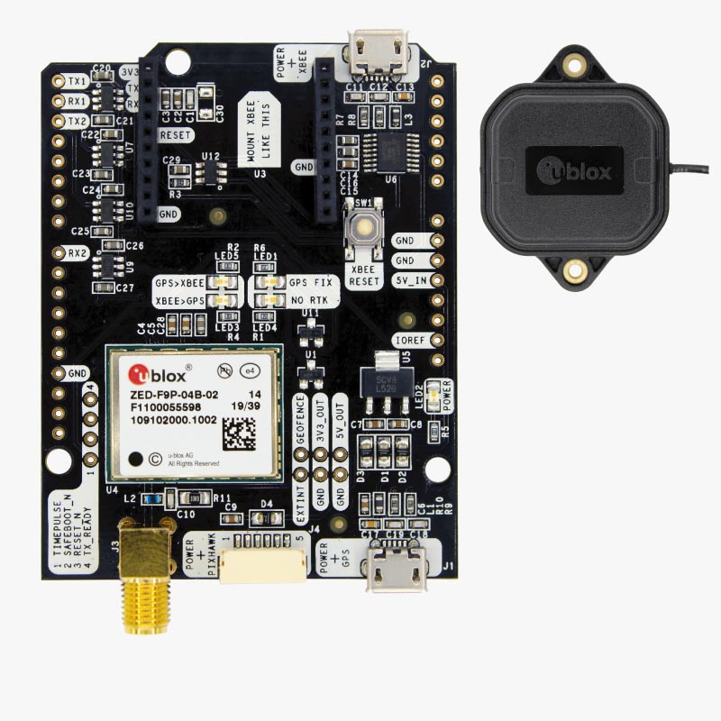
You do not need to have installed Autosteer, you just need a Windows 10/11 tablet, an RTK receiver and antennae, like this:
 www.ardusimple.com

And to download the AgOpenGPS software from here:

 github.com
The Parts
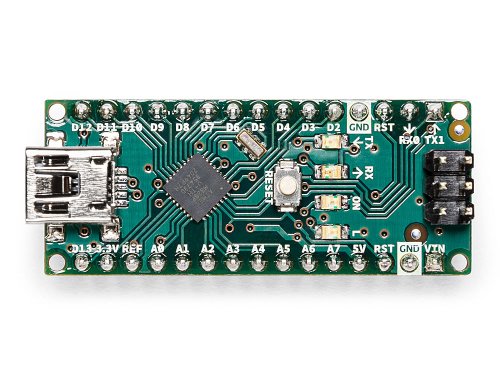
So assuming you have AgOpenGPS setup, be it full autosteer or just guidance you need to build a 'Machine module', so first off we need an Arduino, the code is principally written for an Arduino Nano, (but will work with other Arduino boards but may need minor alterations to reflect the differing number of pin outputs).
So you need to buy one of these:

 store.arduino.cc
Next you need a way of connecting to the Pins on the Arduino, so we need a shield like this:

You'll then need a relay board, if you have a 4 section sprayer you will need 4 relays (however some reverse polarity sprayers will need 2 per section, so 8 relays for 4 sections), we want 5V relays as we will be using the 5V output from the Nano to power it.

Will also need some Dupont cables to connect the shield to the relay board, like this:

You will also need a mini USB cable.
The Build
So first place the Arduino Nano into the Shield, taking care to match the pin labels. So each pin on the Arduino has a screw terminal on the shield.
We can power the Nano in two ways, via the USB cable or via the Vcc and GND pins, in this example we will use USB, since we will be using that to communicate with the AgOpenGPS Software. As we are only operating 4 relays the Nano onboard 5V is comfortably able to handle this, but if powering more relays you should power the relay board with a separate supply.
We then need to use the Dupont cables to connect the Nano pins D13, D5, D6 and D7 with In1, In2, In3 and In4 respectively.
We are also going to use the Arduinos 5V output to power the Relay board, so connect a cable to 5V and Ground and connect these to the Vcc and GND pins on the relay board, like this:

So moving to the relay board, each relay has 3 connections:
COM- Common, this is connected to NC when the relay is not powered and to NO when the relay is activated
NO- Normally Open, this is isolated when the relay is not powered and connected to COM when the relay is powered
NC- Normally Closed, this is connected to COM when the relay is not powered and isolated when the relay is powered
So for this example our sprayer needs a 12V constant input or signal to turn on, so we are going to put 12V to all the COM terminals, in this example I'm using a 5 way Wago connector to distribute an incoming 12V supply to the relays.
We only want the sprayer to receive 12v when the relay is activated so will put a wire into the NO terminal and connect this to the sprayer section on/off switch.
Its entirely up to you how you do this, you could put in NC and need the relay activated to turn the sprayer section off, this is a fails on system, which IMO is not good for a crop sprayer, always prefer fail safe/off. We can invert the relays in the software to our preference.

In this example we are controlling a Knight 24m crop sprayer with 6m sections, the sections are switched by a SPST switch that sends 12V to the sprayer valve, which is a SAFI valve with integrated relay. We will replace the switches in the cab mounted control box with SPDT switches, like this:

The middle terminal on the switch will go to the sprayer valve, the top pin will be connected to the 12V supply in the sprayer control box and the bottom terminal we will connect to with our cable from the Relay NO terminal. In this example the RDS Delta rate controller is spliced into the middle terminal so will receive a signal to tell the rate controller which sections are turned on.
Repeat for the other three sections.
So in this example switch up is manually On, middle is Off and bottom is AgOpenGPS section control. So in practice if spraying manually with AgOpenGPS not operating the middle and bottom positions are off.
Firmware
We now need to install the firmware on the Arduino Nano, to do this you need to download Arduino IDE

 www.arduino.cc
There are countless tutorials and YouTube videos online of how to install firmware or sketch as its known onto an Arduino, so will skate over it.
You need to go to the AgOpenGPS firmware repository here:
 github.com
And download it, then locate this file in the Arduino modules USB folder:

Open the file in Arduino IDE, connect your Nano via USB, select the correct COM port and then click on Upload, you now have the firmware installed.
So we need to connect our machine module via USB cable to our tablet.
It doesn't matter if you are using AgOpenGPS via Ethernet/UDP you can mix and match.
So in AgIO go to the serial connections and connect the Machine module:


You can see here the Machine module is connected on COM 21.
When you plug the USB cable into the tablet/computer, you will hear the relays operate as the Arduino software starts to run, they will toggle, this is perfectly normal.
In the AgOpenGPS settings you need to assign each section to a Pin:

You can have a play in the house/office in Simulator mode with your module plugged in, the relay boards have led lights to indicate when they activated and you will here them clicking.
So that's a quick guide, you then need to put all your parts in an enclosure, like this:

That Arduino shield and relay board are held in place on plastic PCB stands like this, that are epoxy resins to the enclosure:

Then there is a USB panel mount cable like this:

As well as guidance and autosteer, AgOpenGPS is extremely good at auto section control or Machine control as its referred to.
You can control an implement lifting in and out of work on the headland, tramlines engaging and disengaging and turning on and off sections of a sprayer, spreader or seed drill.
You do not need to have installed Autosteer, you just need a Windows 10/11 tablet, an RTK receiver and antennae, like this:
simpleRTK2B - Basic Starter Kit
The Starter Kit allows simple and fast evaluation of Dual Band GNSS (GPS/Galileo/Glonass/Beidou) RTK technology, based on u-blox ZED-F9P module.
And to download the AgOpenGPS software from here:
Releases · farmerbriantee/AgOpenGPS
Ag Precision Mapping, Section Control and Guidance Software - farmerbriantee/AgOpenGPS
github.com
The Parts
So assuming you have AgOpenGPS setup, be it full autosteer or just guidance you need to build a 'Machine module', so first off we need an Arduino, the code is principally written for an Arduino Nano, (but will work with other Arduino boards but may need minor alterations to reflect the differing number of pin outputs).
So you need to buy one of these:
Arduino Nano
The Arduino Nano is a small, complete, and breadboard-friendly board based on the ATmega328 (Arduino Nano 3.x). It has more or less the same functionality of the Arduino Duemilanove, but in a different package. It lacks only a DC power jack, and works with a Mini-B USB cable instead of a...
store.arduino.cc
Next you need a way of connecting to the Pins on the Arduino, so we need a shield like this:
You'll then need a relay board, if you have a 4 section sprayer you will need 4 relays (however some reverse polarity sprayers will need 2 per section, so 8 relays for 4 sections), we want 5V relays as we will be using the 5V output from the Nano to power it.
Will also need some Dupont cables to connect the shield to the relay board, like this:
You will also need a mini USB cable.
The Build
So first place the Arduino Nano into the Shield, taking care to match the pin labels. So each pin on the Arduino has a screw terminal on the shield.
We can power the Nano in two ways, via the USB cable or via the Vcc and GND pins, in this example we will use USB, since we will be using that to communicate with the AgOpenGPS Software. As we are only operating 4 relays the Nano onboard 5V is comfortably able to handle this, but if powering more relays you should power the relay board with a separate supply.
We then need to use the Dupont cables to connect the Nano pins D13, D5, D6 and D7 with In1, In2, In3 and In4 respectively.
We are also going to use the Arduinos 5V output to power the Relay board, so connect a cable to 5V and Ground and connect these to the Vcc and GND pins on the relay board, like this:
So moving to the relay board, each relay has 3 connections:
COM- Common, this is connected to NC when the relay is not powered and to NO when the relay is activated
NO- Normally Open, this is isolated when the relay is not powered and connected to COM when the relay is powered
NC- Normally Closed, this is connected to COM when the relay is not powered and isolated when the relay is powered
So for this example our sprayer needs a 12V constant input or signal to turn on, so we are going to put 12V to all the COM terminals, in this example I'm using a 5 way Wago connector to distribute an incoming 12V supply to the relays.
We only want the sprayer to receive 12v when the relay is activated so will put a wire into the NO terminal and connect this to the sprayer section on/off switch.
Its entirely up to you how you do this, you could put in NC and need the relay activated to turn the sprayer section off, this is a fails on system, which IMO is not good for a crop sprayer, always prefer fail safe/off. We can invert the relays in the software to our preference.
In this example we are controlling a Knight 24m crop sprayer with 6m sections, the sections are switched by a SPST switch that sends 12V to the sprayer valve, which is a SAFI valve with integrated relay. We will replace the switches in the cab mounted control box with SPDT switches, like this:
The middle terminal on the switch will go to the sprayer valve, the top pin will be connected to the 12V supply in the sprayer control box and the bottom terminal we will connect to with our cable from the Relay NO terminal. In this example the RDS Delta rate controller is spliced into the middle terminal so will receive a signal to tell the rate controller which sections are turned on.
Repeat for the other three sections.
So in this example switch up is manually On, middle is Off and bottom is AgOpenGPS section control. So in practice if spraying manually with AgOpenGPS not operating the middle and bottom positions are off.
Firmware
We now need to install the firmware on the Arduino Nano, to do this you need to download Arduino IDE
Software
Open-source electronic prototyping platform enabling users to create interactive electronic objects.
www.arduino.cc
There are countless tutorials and YouTube videos online of how to install firmware or sketch as its known onto an Arduino, so will skate over it.
You need to go to the AgOpenGPS firmware repository here:
GitHub - farmerbriantee/AgOpenGPS_Boards: Hardware PCB and firmware for AgOpenGPS Software
Hardware PCB and firmware for AgOpenGPS Software. Contribute to farmerbriantee/AgOpenGPS_Boards development by creating an account on GitHub.
github.com
And download it, then locate this file in the Arduino modules USB folder:
Open the file in Arduino IDE, connect your Nano via USB, select the correct COM port and then click on Upload, you now have the firmware installed.
So we need to connect our machine module via USB cable to our tablet.
It doesn't matter if you are using AgOpenGPS via Ethernet/UDP you can mix and match.
So in AgIO go to the serial connections and connect the Machine module:
You can see here the Machine module is connected on COM 21.
When you plug the USB cable into the tablet/computer, you will hear the relays operate as the Arduino software starts to run, they will toggle, this is perfectly normal.
In the AgOpenGPS settings you need to assign each section to a Pin:
You can have a play in the house/office in Simulator mode with your module plugged in, the relay boards have led lights to indicate when they activated and you will here them clicking.
So that's a quick guide, you then need to put all your parts in an enclosure, like this:
That Arduino shield and relay board are held in place on plastic PCB stands like this, that are epoxy resins to the enclosure:
Then there is a USB panel mount cable like this:
Attachments

Last edited:
")