22mm dia hole and getting a correct distance on a mill?

PuG

Member
Good morning, after some machining advise.

I need to drill two holes 300mm apart in steel bar to a N6, 22mm tolerance (nominally 21.98mm) for press fitting needle bearings.

32 holes in total, 2 in each steel bar.

The bars are going to be laser cut for there shape - in the previous design I had a large hole cut via a laser in the correct places then drilled out, but the 22mm drill tolerance is relatively poor, though fine for two arms. On top of that the 300mm measurement drifted ever so slightly due to laser cut irregularity and human incompetence on my behalf.

I'm not a machinist, so I want a practical solution that's repeatable and easy.

For the next 16 arms, I was thinking of laser cutting a very small diameter hole. Align one of them on the mill using a spigot, tar the DRO. Machine the hole with a cutter, move it 300mm, machine the second hole, fit & repeat with a reamer? to n6 tolerance.

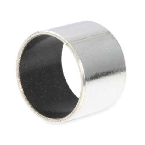
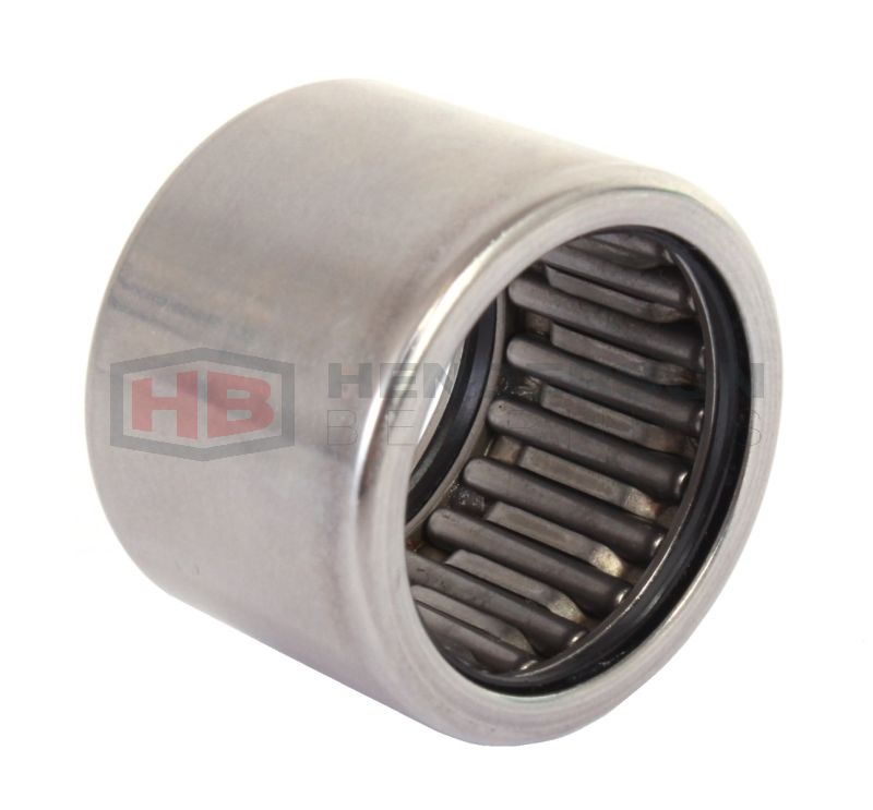
Can you get cutters that would be to the right tolerance save having to use a reamer? this is the bearing i'm trying to fit:


In my first attempt they easy slid in the cut hole, bit on the easy to fit side, and they say it should be press fitted?

Reamer: https://www.cutwel.co.uk/hole-makin...ank-machine-chucking-reamer-yg-1-k2102-series

Cheers, James


More information, I will be doing two bars at once, they will have a steel plate welded in between spacing them, and I will be cutting 132mm on the spindle to clear both plates at once and to make sure everything is aligned after welding deviation.
 
Last edited:

TheTallGuy

Member
Location
Cambridgeshire
You'll struggle to get to tolerance without reaming or professional grade successive drills. For many applications it's not necessarily that crucial for the fit to be that precise & a dab of high strength retainer does the job for stopping the race from moving. The most important part is usually the angular alignment & axial mismatch as this puts unwanted forces onto the bearing which can lead to premature failure.

For getting consistent spacing it will depend on your mill & its capabilities. I'd aim to create a jig for repeatable clamping & use a DRO to validate the positions. I would avoid using laser cut holes to pilot from as if they aren't perfect & correctly aligned they will cause the drill to deviate from true, as could burrs etc. The correct approach is to use a spot/centre drill to create a cone for the pilot drill to pick up on, then use a series of drills to get up to undersized before putting the reamer through. A trick that I have used before - especially when there is an existing pilot hole of questionable position is to use an end mill as this avoids the problem of drill point going off course, but depth of cut & cutter wear can become an issue.
 

PuG

Member
Thank you for the reply. I could bore the holes with perhaps an end mill cutter straight to 22? and as you say just use some bearing lock tight or equivalent. (or 21.8 and ream) Saves having to drill up and quick. My idea with just laser cutting a point hole for the first frame of reference, given I would try and do them in pairs after welding so the angular alignment would be the same, and the 300mm distance between would always correspond - but equally could etch and drill small pilot holes. Yes on a jig, I was trying to think tonight how to clamp it.

I was half thinking put the bed attachments (for milling/cutting etc) on my Myford Super7 lathe, its probably easier clamping it down horizontally than holding vertical with the cheap Chinese one.

When I cock it up I'll post pictures :)
 

case study

Member
Thank you for the reply. I could bore the holes with perhaps an end mill cutter straight to 22? and as you say just use some bearing lock tight or equivalent. (or 21.8 and ream) Saves having to drill up and quick. My idea with just laser cutting a point hole for the first frame of reference, given I would try and do them in pairs after welding so the angular alignment would be the same, and the 300mm distance between would always correspond - but equally could etch and drill small pilot holes. Yes on a jig, I was trying to think tonight how to clamp it.

I was half thinking put the bed attachments (for milling/cutting etc) on my Myford Super7 lathe, its probably easier clamping it down horizontally than holding vertical with the cheap Chinese one.

When I cock it up I'll post pictures :)
If the spindle of you're lathe has a morse taper,you could use a boring head,a small enough one should be easy to get on ebay,a Chinese one might be precise enough and not too expensive.
 

tinman

Member
Location
Ulster
What the tall guy says is right about pre marking holes with the lazer, i wouldn't do it either, on top of that id assume that pre cutting even a small guide hold will harden the surface area of the hole and anything following it to bore it out larger wont thank you for it.
id be inclined to cut the plates out and bore my own holes then.

So im kinda with you on what your doing but not 100% either.
how big are the plates your looking to work on, overall size wise?
what thickness are they, given your bearing is 16mm wide im assuming that or wider at least?
what is expected of the bearings when fitted, load wise and whats retaining the rod thats to run through the needle bearings?

21.98 is fairly close to 55/64 in imperial, you can get reamers in that size, as to the finished hole it leaves for the fitment of the bearing one couldn't be so sure until you would try it.
loctite 648 will be your friend after that if not.

Im taking it that the holes/frame will be spaced 132mm wide, that the outside dimensions of the unit?, 2 x 16mm bearings=32mm and 100mm between the plates which will be 16mm each?

If you couldn't turn up a imperial reamer and no guarantee it would be the exact size then id be looking at boring out the plates to as close to the size as possible and use a boring head on the mill to finish it out to 21.98 for the bearing, set that up on a test piece first and go from there altho a boring head isnt going to like boring out a hole 140mm from the head, there will be some deflection that would have to be taken into account.

Failing that tack the plates together first and bore them out to size, turn say 150mm long rods down to 21.98 and insert them through the holes for alignment when you'd have the spacer in, maybe turn bosses for them to go into on the back side so they sit square and make up a jig on the likes of a flat plate so nothing can move and weld it then, they will be a bit tight to remove when finished and allow for that when making the "guide rods", ie, turn a smaller diameter on the end so you can knock them out without mushrooming the head of them, maybe have a hole in the bottom of the jig plate so you can knock them out from behind just in case.

don't know if that's any help but it might be some ideas.
 

PuG

Member
Good morning, morse taper 4. The mill:

What I decided last night was to have 20mm holes cut (marked at 15 for the moment) with the laser, then end mill straight to 22mm given Drill Service (Horley) Ltd offer an extra long bit to a high tolerance reasonably priced (£35). But I hadn't thought about the steel being hardened by the heat cycle. I suppose I could anneal it.

Thanks for the suggestions, its good but I'm not keen on using a boring head. I would prefer to end mill to say 21 then use a reamer to finish. I've found several to the right size and length, bit more expensive. I do have a massive box of them from Grandpa which I need to rummage through to see what he had.

Lastly a hollow mill bit like below:

Just there too short but I could prep a hole smaller dia instead of laser cutting, then try and end mill.

Regardless my mill only goes to 125mm depth on the spindle so I'm going to have to move the tooling or leave an end cap which actually suits me.

Thanks for the replies, ideas.


Untitled-1.jpg
 

TheTallGuy

Member
Location
Cambridgeshire
Making that depth of cut with long drills/mills & reamer is a bit of a chancey thing. The hole in the bottom piece is likely to be somewhat larger than in the top piece & you're going to have to have the head trammed in absolutely spot on in all planes or the holes will be at an angle & over that distance the offset will be appreciable. You would also need spacer blocks in near the holes to prevent deflection when applying cutting forces.

I think that my approach would be similar to @tinman above. I'd make a jig to hold two plates flat together for drilling & reaming then a second jig for assembly using guide rods in those holes to maintain alignment during assembly; if the centre spacer/web piece is being welded then some extra features on the jig/setup to assist clamping & warp control would be useful. Something else that will require a bit of consideration is how you are going to fit the bearings into the holes & at what stage.
 

tinman

Member
Location
Ulster
The tallguy and I are on the same page here.
Drill the two plates together then assemble in a jig, get 2 lugs/wings cut on the spacer plate either side and matching holes in the plates to aid in assembly before welding, make a jig to hold everything including 21.98 pins in place to keep it all aligned, tack it in places to prevent too much of a pull and weld other side to compensate the pull from the tacks, dont go welding it all on one side and expect the other side to pull it back when its welded.

keep the wings depth to say 15mm so when they would fit into the 20mm plate you have 5mm of a void to fill with weld, it ill look more professional.

thing is, its a very heavy bracket in total to be having needle roller bearings that size in it, could you get away with plain teflon coated bearings, they will press into a straight size, ie 22mm, i dont know whats expected of the shaft through the needle bearings so cant say really.

To give you an idea, this is a jig i made up a few weeks ago, pins turned down to set a height to keep all parts aligned, also for repetition, lugs on the jig welded solid so it could all be assembled and bolted tight together with a shim to allow for free movement after welding and to allow for any slight distortion, a jig is the way to go for repetitive work.
 

Attachments

  • IMG_20200204_111815.jpg
    IMG_20200204_111815.jpg
    573.3 KB · Views: 0
  • IMG_20200204_195827.jpg
    IMG_20200204_195827.jpg
    334.6 KB · Views: 0

PuG

Member
Thanks TheTallGuy, Tinman for the information and pictures. Yes I'm going to do as you guys suggest regarding drilling and making up a jig. A good idea on the lugs.

For the bearings I'm making a seed drill which has 16 of these arms (2 per set), and our decision was if they had been standard bronze it would be hell of a allot of grease nipples in awkward spots, plus it might become grinding paste, I'm concerned also for alignment problems.. the actual pull loading are nothing amazing on each set of these but it will be forcing it in a lateral direction. The bearings are rated to 700kg's each. I was using another drill as an example given they also had needle bearings.

This is the one I want to fit: https://www.skf.com/group/products/rolling-bearings/roller-bearings/needle-roller-bearings/drawn-cup-needle-roller-bearings/productid-HK 1616.2RS.

I've just done some googling, and I suppose something like this could be used used instead. Just I'm nervous on which would be better long term. Obviously below is much cheaper and easier for me to assemble.

 
Last edited:

Andrew

Never Forgotten
Honorary Member
Location
Huntingdon, UK
Looking at the problem from a different perspective, could you put the bearing bits on the piece that fits ‘inside’ your brackets. Then bolt the pin to your brackets to stop it turning. It’s a lot easier to machine one boss than two holes far apart?
I appreciate that may not be possible though.
 

PuG

Member
Hi Andrew, unfortunately the bit that goes in between is another two plates 15mm thick respectively, and then a hydraulic ram sandwiched in between to make a parallelogram movement. The problem is its fitting allot of stuff into a small area... I will post some pictures sometime when I get a chance to sit down as I built a prototype last month. Cheers
 

tinman

Member
Location
Ulster
As for the plain bearings, used extensivley in agri world today, in the pic, its a headstock i repaired out of a hedgecutter that has a telescopic arm on it, 7.5mtr reach iirc, thats just the two on the pivot there but there was also the same on the main arms, the ram boss, the elbow on the boom, all over her tbh, them and nylon bearings.

id use the plain bearings often enough, used a lot in front loaders, there's a few different flavors but principally all the same to some degree.
Id buy a right few bearings from this crowd, find them good as are the prices.
 

Attachments

  • IMG_20191123_200501.jpg
    IMG_20191123_200501.jpg
    166.9 KB · Views: 0

PuG

Member
Thanks for the link to the bearings, much better price than SKF. Has anyone used Zen before? I know there Chinese and normally avoided however they do have TUV certification in Germany, and the equivalent needle bearing outer housing is done to B2 tolerance. So its 22 +0.38 rather than N6. So I could probably get away with one pass using the end mill.

Looks a smart repair, very tidy. Amazingly thin steel for the weight of a hedge trimmer head!
 

tinman

Member
Location
Ulster
Looks a smart repair, very tidy. Amazingly thin steel for the weight of a hedge trimmer head!
i hardness tested it at 380hbw so i replaced what was damaged with weldox 400 which is an education to work in itself.
20mm plates so it may look on the light side but the strenght is there.
 

john63

Member
Mixed Farmer
Location
East Lincs
As for the plain bearings, used extensivley in agri world today, in the pic, its a headstock i repaired out of a hedgecutter that has a telescopic arm on it, 7.5mtr reach iirc, thats just the two on the pivot there but there was also the same on the main arms, the ram boss, the elbow on the boom, all over her tbh, them and nylon bearings.

id use the plain bearings often enough, used a lot in front loaders, there's a few different flavors but principally all the same to some degree.
Id buy a right few bearings from this crowd, find them good as are the prices.

They look like GGB DX bushes to me. They require grease, but there are greaseless alternatives such as the DU. Companies like IGUS also have a wide range of plastic bushes.
 

tinman

Member
Location
Ulster
They look like GGB DX bushes to me. They require grease, but there are greaseless alternatives such as the DU. Companies like IGUS also have a wide range of plastic bushes.
DX polimer plain bearing in that headstock.
just showing pug what the likes of a plain bearings are used on and the weights involved there.
the DU has a coating of graphite that rubs on the shaft allowing for somewhat more of a drier application.

igus have plastic bushings but maybe more linear inclined than carrying a big weight, ive seen their stuff at shows and its fancy no doubt.
 

SFI - What % were you taking out of production?

  • 0 %

    Votes: 77 43.5%
  • Up to 25%

    Votes: 62 35.0%
  • 25-50%

    Votes: 28 15.8%
  • 50-75%

    Votes: 3 1.7%
  • 75-100%

    Votes: 3 1.7%
  • 100% I’ve had enough of farming!

    Votes: 4 2.3%

Red Tractor drops launch of green farming scheme amid anger from farmers

  • 1,286
  • 1
As reported in Independent


quote: “Red Tractor has confirmed it is dropping plans to launch its green farming assurance standard in April“

read the TFF thread here: https://thefarmingforum.co.uk/index.php?threads/gfc-was-to-go-ahead-now-not-going-ahead.405234/
Top