As I wrote upthread but relevant here, a good bottle jack under the sump with the front wheels chocked and a large trolley jack lifting under the back of the tractor, to move with the back end as it is all rolled backward could have replaced my tractor splitting rails.


You are using an out of date browser. It may not display this or other websites correctly.
You should upgrade or use an alternative browser.
You should upgrade or use an alternative browser.
Massey Ferguson 500 series hydraulics
- Thread starter TC85336
- Start date
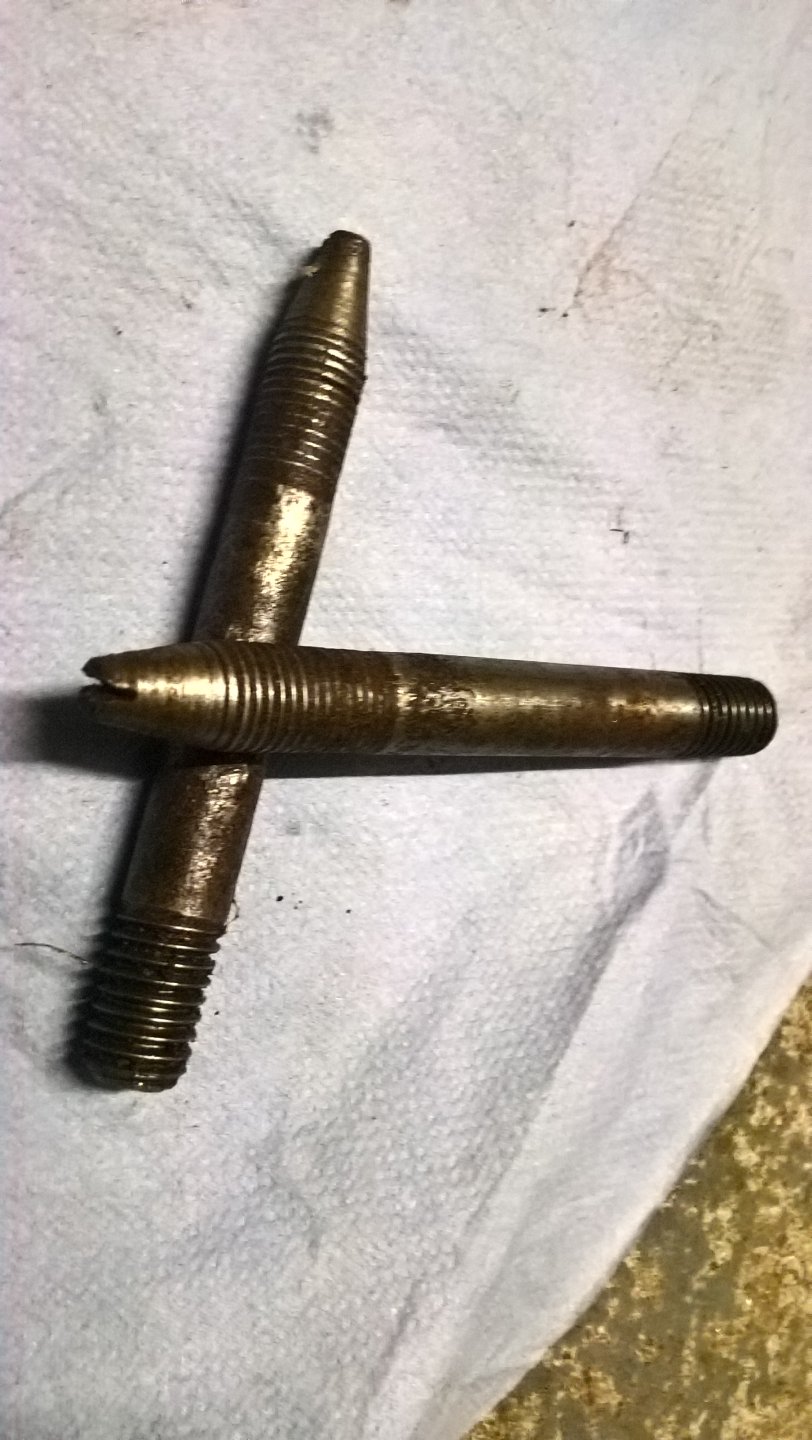
Another thing needed for rejoining after splitting, I used the MF recommended guide studs. You will see I increased F to 4 1/2" and D to 1". I used a couple of old 7/16 UNF bolts, cut the head off and threaded the stub 7/16 UNC and turned the taper on the end.
I also used them for removal and replacement of the top cover. On removal to make sure I did not whack that delicate looking arm as it came up and going back, just to keep everything in line. In fact, if I did the top cover again, I would make up four of them so that the cover is going back completely square, that butterfly on the top of the pressure control valve is easily knocked out of where it is meant to be.
I also used them for removal and replacement of the top cover. On removal to make sure I did not whack that delicate looking arm as it came up and going back, just to keep everything in line. In fact, if I did the top cover again, I would make up four of them so that the cover is going back completely square, that butterfly on the top of the pressure control valve is easily knocked out of where it is meant to be.
Attachments


- Location
- Cambs/Suffolk/Norfolk
Hello am I right in thinking this is Tony? I recognise your in-depth writing style and the tractor makes sense too.
You purchased a Foster digger from me a couple of years ago. Glad to see the tractor finally all working out all the best.
You purchased a Foster digger from me a couple of years ago. Glad to see the tractor finally all working out
all the best.The Foster digger is brilliant and it was a great purchase, thank you, particularly for loading it on the trailer. It has just a pity that moving it all around was so difficult because the lift arms were useless. I did a couple of jobs with it but am looking forward this year to really making progress. I have yet to hitch it up now the lift arms are working properly. I purchased a couple of extra buckets for it direct from Fosters. They were very helpful and wanted to see the serial number. They exhibited that digger on their stand it at the Highland Show that year before delivery straight after the show.
Attachments


Before I finish on problems re "splitting" there is a further issue, which undoubtedly caught out the unwary on many an occasion and caused a design change. Once again, inadequate editing of the workshop manual by the MF service department exacerbates the issue. On 500 series tractors with no auxiliary pump, ie no IPTO, no Multipower, no extra hydraulics, with just the lift hydraulics the split just boils down to removing all those things on the outside you can see holding the two parts together. However the 500 series tractors with any of: an IPTO, Mutlipower or auxiliary hydraulics there is an oil cooler at the front of the tractor that oil needs to get to. Remember first off there is no section in the workshop manual for splitting the tractor between spacer housing and centre housing for the 590, just one section for the 550 & 560 and another for the 565, 575 & 560 (again!) Attached in the relevant picture and the text states "11 Disconnect the oil pipe, (if fitted)." So I looked at my tractor and no oil pipe was fitted so way to go, unbolt and get something big to pull the two sections apart, right? Wrong. Nowhere in "splitting the tractor2 is there any mention of what you might do if there is no oil pipe No 11 fitted and yet, magically, there is an oil cooler at the front of the tractor that must be getting oil to it somehow.
Attachments

Last edited:
Cowabunga
Member
- Location
- Ceredigion,Wales
Surely you can follow the pipes back from the oil cooler to their source?Nowhere in "splitting the tracto"r is there any mention of what you might do if there is no oil pipe No 11 fitted and yet, magically, there is an oil cooler at the front of the tractor that must be getting oil to it somehow.
The Parts list provides, not very clearly, the evidence as to how that oil is getting to the front of the tractor. Attached is P172 of the MF parts list.
The auxiliary pump is in RED.
We see item 36 in the parts list, yellow, is our item 11 from the workshop manual - "remove if fitted"
We also see the associated pipes to this arrangement.
Item 31, green is the pipe taking supply from the pump to the side of the centre casing to feed our pipe to "remove if fitted".
Item 44, also in green, takes the supply forward along the side of the tractor.
But have a look closely at that page. In a box all on its own is item 30 which is simply described as "Hydraulic Hose" And it is not like the "up to" and "From" data matches. 30 is up to 377724 and 31 is after 654367.
So what is going on?
It is more mistakes that is what is going on. A job not completed to a satisfactory standard. Elsewhere on the parts list page there is "From 377724" for pipes 36 and 44 for example.
So OK there are mistakes on both the parts list and the workshop manual and pipe No 30, in its little box, exists. But where does it go where is it fitted?
Well I was not going to pull the tractor apart until I had found it.
Attachments

Well taking the top cover off and things, whilst not clear, became apparent.
Oil gets to the oil cooler and then onto the multipower clutch/pressure maintaining valve (8sp) either via the external pipe shown in the workshop manual or via the pipe 30, not referenced in the workshop manual, that runs from the centre housing through the inside of the gearbox, above the gear train, a route totally unobservable to any human not equipped with X-ray vision, before it pops out under the cab floor just ahead of the gear selector levers.
So the workshop manual can find time, space and a diagram, to show us the totally obvious but does not mention the alternate hidden pipe inside the tractor.
OK so the simple message is, don't pull the tractor into two bits until that pipe is disconnected, wherever it runs.
I wonder just how many mechanics followed the workshop manual to the letter and then, when the two parts were about 2" apart and not wanting to go any further, found that they had given themselves another, very expensive job, change pipe 30 which was now deformed out of shape?
Obviously that happened because MF changed the design to run the pipe externally.
If brute force had been applied and the two parts came apart whether they liked it or not, then pipe 30 would be broken and have to be replaced.
More critically, was the "solution" when discovering this error, to shove the pipe sort of back into shape-ish and hope it did not leak and would last a few months until the irate owner returned and the "new fault" could be blamed on "MF hydraulics are shocking, don't last 10 minutes mate" ?
Attachments


Before I finish on splitting let me describe something for the novice, which I am sure many of the more experienced hands, on here, do as routine.
My tractor had been split in the past and some sort of goo put in to help the castings seal against each other. Obviously this was an addition alongside the trick of making up for the fact that some hard-to-get-at bolts were just over finger tight and the ones nearby, that were easy to access, were over tightened to compensate - "its all about averages mate."
Now when all was released and the two halves should have come apart, it was having none of it. In this picture you can see the chain of the hoist horizontally placed, that did not pull the two halves apart.
The expedient is to anticipate this turn of events and not undo all the bolts and simply pull harder, until something "gives".
Fit the two guides half way up the joint and four bolts. Two bolts are fitted to the top flange and positioned so that the heads are 1/8" (3mm) clear of the casting and two more similarly fitted in the lower flange.
Then, without great load on the chain, simply jack up the two jacks on the tractor splitting rail. Do this, evenly, in small increments, until the joint parts at the top and the flange of the casting moves to the underneath of the head of the bolts on the top flange. Then lower the two jacks, evenly, in small increments until the lower flange does likewise.
Adjust the jacks until the gap in the joint face is even top and bottom.
Now those four bolts can be undone further and then the two halves pulled apart a bit more. Without drama or angst the tractor is split into two halves.
I am sure there was so much jointing goo on my vehicle I could have driven my tractor for days without any bolts, but that was not something I wished to put to the test!
Attachments

Cowabunga
Member
- Location
- Ceredigion,Wales
The relatively small bolts, a legacy from when tractors and implements were far smaller, are/were notorious for coming loose. That is particularly bad because one side is hidden behind the fuel tank. If I remember correctly these tractors had gaskets between chassis sections and the main reason for them coming loose was that the gaskets settled. Most modern tractors have more precision machined castings and only a thin sealant between sections to make the joints oil proof.
That's what I thought as well. So the cab floor came up; eventually. All those sheared bolts and captive nuts I destroyed - joy. That let me see that there were two pipes popping out of the front of the gearbox. Both were routed to the oil cooler. One was obviously a supply and one a return. One fitted to the multipower valve block and the other came out of a rubber moulding fitted to the gearbox.Surely you can follow the pipes back from the oil cooler to their source?
At that stage, with two pumps and three separate hydraulic systems already on the score sheet, I was not ruling out the chance that there was some sort of additional pump mounted on the primary shaft at the front of the gearbox. Certainly both the pipes I could now see, seemed to come from this region. The good news was there was no such thing.
Hot tip - leave the cab floor in place.
Last edited:
Cowabunga
Member
- Location
- Ceredigion,Wales
The method taught by MF when it came to splitting the 500 series was that the cab usually only needed to be dismounted at either the front or back. In your case the cab would be left attached at the front mountings, the fuel tank removed, the chassis unstitched and wheeled out from under the back using a trolley, with the rear of the cab supported level. It would seldom need to be split at the flywheel and further back in one operation. If split at the flywheel the linkages, pipes and cables would be split just in front of the cab and the front pushed forward. This would be the case when changing the clutch.
Worth doing here the low pressure system description. Two common ports on auxiliary pump. One to the front and one to the IPTO.
The IPTO is a dead leg with no relief valve in it. A practice used in other industries was to design in a gap in piston rings to allow a certain amount of fluid "leakage" so that a small flow was always maintained. Certainly the valve on the shaft of the IPTO body sealed with circlips will allow a small flow of oil when in good condition - as mine now or a very large flow if worn - as mine was previously.
The system to the front is via pipe, internal or external, to the front of gearbox. Front of gearbox to oil filter. Filter to cooler. Cooler to valve block for multipower. As MFAndy, so correctly, advises the valve block of the multipower features a pressure maintaining valve so that when multipower is not engaged oil is allowed to exit the cooler via this valve back into the front of the gearbox. When multipower is engaged there is another dead leg to the multipower clutch but the pressure maintaining valve effect of the valve block would still act.
Excessive leakage of either the multipower clutch or IPTO clutch will cause system pressure to fall below that specified.
For 8 spped tractors there is an inline pressure maintaining valve on the return from the cooler. The pipe then just returns to the front of the gearbox to discharge.
at Multipower clutch
Multipower in either high or low
Idling 100-230 psi
2000 rpm 230-270 psi
At IPTO
IPTO not selected - 0 psi
2000 rpm IPTO selected 200-250 psi
As we know fluid pressure acts equally in all directions and there can be no justification for different pressures quoted for the 2000 rpm figures. I connected up my 0-400 psi gauge at both the IPTO and the multipower clutch and the pressures I saw were identical irrespective of location but dependent on engine speed and control settings.
I did not bother with the test of the low pressure relief valve. According to MF with IPTO not selected (no oil flow rearwards and the pressure gauge fitted as a stop in the pipe to the filter/cooler the relief valve on the pump should be 700 minimum psi at idle and 1000 maximum psi at 200 RPM. Should the output not match these figures, Agriline advise this relief valve is adjustable. One can then split the tractor and remove the pump and take a complete guess at how much to adjust the relief valve and then put it all back and repeat the test and observe. Should one's adjustment be too much/insufficient, presumably one keeps repeating the process, split, adjust, rebuild test.
Since these pressures or anything down to 280 psi is above that the pressure maintaining valve maintains, it is all irrelevant. I let it be.
So as designed the oil filter, filters just part of the oil that flows through the low pressure system and does not filter oil that flows through the lift pump or the high pressure auxiliary hydraulics.
The design is a bit like those car engines of the 1930s through to the 1950s with a bleed from the oil gallery through the oil filter back into the sump. In some sad cases there was no pressure maintaining valve, simple filter flow restriction, which would vary with time, being the only limiting element.
Attachments

Oliveau
Member
- Location
- Indre et Loire, France
Looking at the photos I can't help but think that I would have removed the cab to make the splitting job s bit easier.
Talking of MF crap, back in 1973, in a new job I had a new 188 - What a load of complete & utter crap! It got through engine oil like an alcoholic let loose in a brewery. The hydraulics, IPTO and Multipower used to fail regularly - not good on steep downland with no engine braking! And the noise in the cab was horrendous . In the end it disgraced itself by not running the double chop forager with enough power/speed to blow grass up the spout. The gaffer wouldn't believe me until he saw it for himself, then he got back into his Range Rover and went straight down to TH White and ordered a 7000. As it was the time of the 3 day week I had to wait 9 months for it, but it then arrived as the first DP model in the area, and with twin spool valves. I was such a happy bunny!
Talking of MF crap, back in 1973, in a new job I had a new 188 - What a load of complete & utter crap! It got through engine oil like an alcoholic let loose in a brewery. The hydraulics, IPTO and Multipower used to fail regularly - not good on steep downland with no engine braking! And the noise in the cab was horrendous . In the end it disgraced itself by not running the double chop forager with enough power/speed to blow grass up the spout. The gaffer wouldn't believe me until he saw it for himself, then he got back into his Range Rover and went straight down to TH White and ordered a 7000. As it was the time of the 3 day week I had to wait 9 months for it, but it then arrived as the first DP model in the area, and with twin spool valves. I was such a happy bunny!
Easy to be critical of the workshop manual and parts books but they would have been right on the day they were made. The tractors had a production run of years and were continually updated and improved rendering the books out of date.
How, where, when did you find what workshop manual? It's been a long time since I saw one but don't recall any reference to a 560 model in the UK one I used. Certainly the training course notes didn't mention the 560.
Which also reminds me that the manuals were to aid the factory trained mechanics who would work on these machines every day and not designed for a dIYer to fix his one machine at home.
May Event: The most profitable farm diversification strategy 2024 - Mobile Data Centres
Apr
02
- 2,682
- 49
With just a internet connection and a plug socket you too can join over 70 farms currently earning up to £1.27 ppkw ~ 201% ROI
Register Here: https://www.eventbrite.com/e/the-mo...2024-mobile-data-centres-tickets-871045770347
Tuesday, May 21 · 10am - 2pm GMT+1
Location: Village Hotel Bury, Rochdale Road, Bury, BL9 7BQ
The Farming Forum has teamed up with the award winning hardware manufacturer Easy Compute to bring you an educational talk about how AI and blockchain technology is helping farmers to diversify their land.
Over the past 7 years, Easy Compute have been working with farmers, agricultural businesses, and renewable energy farms all across the UK to help turn leftover space into mini data centres. With...