• Welcome to The Farming Forum!

    As part of this update, we have made a change to the login and registration process. If you are experiences any problems, please email [email protected] with the details so we can resolve any issues.

Alternator question.

Dave W

Member
Location
chesterfield
Got a tiny little kubota 2 cylinder engine with this alternator on it and a separate voltage regulator.
Question is should it charge at the nominal 14.5v like a regular alternator?
I'm only getting max 12.5v with no load on the system (Engine would run without battery connected)
9CDA3941-4F74-4AA1-92AB-147C36DC2488.png
 
Where's @Mursal .

I think I would expect to find around 14v on a good battery
12.6v across the terminals for a fully charged battery at standstill and anywhere from 13.8 to 14.2v when running (charge being delivered). Typically.

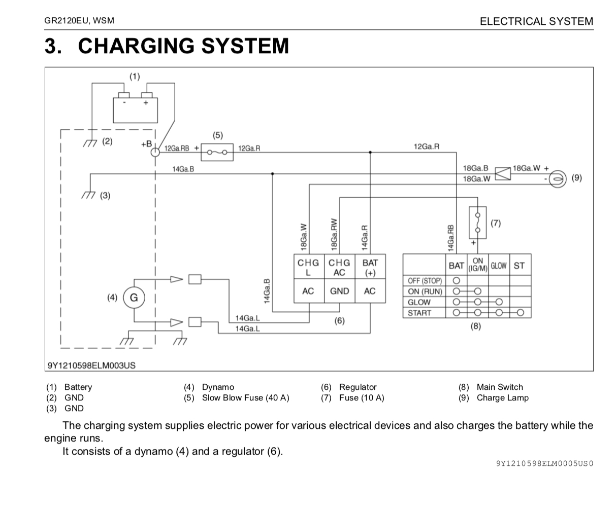
But check the Kubota specs above - this is from my lawnmowers WSM, but Daves will be about the same.

I’ll check the dynamo, regulator output / battery terminal voltage on my Kubota ride on a bit later on and see how they stack up.
 
Got a tiny little kubota 2 cylinder engine with this alternator on it and a separate voltage regulator.
Question is should it charge at the nominal 14.5v like a regular alternator?
I'm only getting max 12.5v with no load on the system (Engine would run without battery connected)
9CDA3941-4F74-4AA1-92AB-147C36DC2488.png
Kubota workshop manual spec above suggests you should be seeing 14 to 15v from the regulator....

Check the dynamo AC output voltage is @ > 20v too
 

Dave W

Member
Location
chesterfield
Kubota workshop manual spec above suggests you should be seeing 14 to 15v from the regulator....

Check the dynamo AC output voltage is @ > 20v too
Thanks. That's answered what I needed to know.
I was half hoping it was only a trickle charge type thing and only put out 12v but looks like somethings fooked.


So will it be dynamo or regulator?
One thing I noticed was the dynamo wasn't free spinning. There were magnets that held it in certain positions. Is that how they are? Definitely not bearings tight
 
So will it be dynamo or regulator?
One thing I noticed was the dynamo wasn't free spinning. There were magnets that held it in certain positions. Is that how they are? Definitely not bearings tight
Yes a dynamo has permanent magnets on the stator. So as it rotates it will ‘stick’ as the rotor and stator magnets align. An alternator uses a series of windings to create the magnetic field in the stator, so it’s comparatively smooth to turn by hand.

Check the dynamo AC output - reg can only work if it’s getting sufficient voltage.
 
Thanks. That's answered what I needed to know.
I was half hoping it was only a trickle charge type thing and only put out 12v but looks like somethings fooked.


So will it be dynamo or regulator?
One thing I noticed was the dynamo wasn't free spinning. There were magnets that held it in certain positions. Is that how they are? Definitely not bearings tight
So to compare with approx same setup here:

A steady 14.6v out of the regulator / across the battery with engine running - no change to output voltage with revs. Same reading from idle to full revs.

Dynamo/generator output varies from 14 VAC (idle) to 37 VAC (full revs)

DCBAD571-14FE-4C46-8220-CE69E100673B.jpeg
 
As above and also worth checking fuse 5 and 7 on the above diagram from @Pheasant Surprise.
Earth point 3 would be next and 6 on the same diagram.

Can be extremely difficult to pin point a fault when the regulator is external from the alternator.
Yeah definitely. If the main slow blow fuse (5) is gone then there will be nothing delivered from the regulator / charging system. So with engine running, the only voltage across the battery terminals would be from the (resting) battery itself, nothing from charge system.

Also if the dynamo is completely disconnected, the regulator should put on the charge lamp (or there should be 12v present across the lamp holder) while the engine is running.
 

Dave W

Member
Location
chesterfield
As above and also worth checking fuse 5 and 7 on the above diagram from @Pheasant Surprise.
Earth point 3 would be next and 6 on the same diagram.

Can be extremely difficult to pin point a fault when the regulator is external from the alternator.
Yeah definitely. If the main slow blow fuse (5) is gone then there will be nothing delivered from the regulator / charging system. So with engine running, the only voltage across the battery terminals would be from the (resting) battery itself, nothing from charge system.

Also if the dynamo is completely disconnected, the regulator should put on the charge lamp (or there should be 12v present across the lamp holder) while the engine is running.
Unfortunately its on a roller from local cricket club. Wiring diagram above won't apply sadly. The basic principles in the workshop manual should sort it though
 

Mursal

Member
If you have AC voltage coming out of the alternator (measured across the two wires), put a DC voltmeter across the +BAT pin and earth on the regulator and you should have charging voltage (above 13Volts, varying with revs).
If you have AC and no DC suspect wiring or regulator.

Hope this helps a bit .........
 

How is your SFI 24 application progressing?

  • havn't been invited to apply

    Votes: 30 34.5%
  • have been invited to apply

    Votes: 17 19.5%
  • applied but not yet accepted

    Votes: 29 33.3%
  • agreement up and running

    Votes: 11 12.6%

Webinar: Expanded Sustainable Farming Incentive offer 2024 -26th Sept

  • 2,562
  • 50
On Thursday 26th September, we’re holding a webinar for farmers to go through the guidance, actions and detail for the expanded Sustainable Farming Incentive (SFI) offer. This was planned for end of May, but had to be delayed due to the general election. We apologise about that.

Farming and Countryside Programme Director, Janet Hughes will be joined by policy leads working on SFI, and colleagues from the Rural Payment Agency and Catchment Sensitive Farming.

This webinar will be...
Back
Top